
- Interactive 3D technology
- Use cases
-
Case studies
-
-
- Fashion
- Zegna X
-
- Automotive
- PEI Mobility
- UP Design
-
-
- Resources
- FAQ
- The Company
- Contacts
3D printing files are the essential bridge between a creative idea and a physical object, translating digital models into instructions that 3D printers can understand. Unlike traditional image files, which merely represent two-dimensional surfaces, 3D printing files contain complete information about the object’s three-dimensional geometry, making it possible to materialize virtually any conceivable shape.
3D printing files are the essential bridge between a creative idea and a physical object, translating digital models into instructions that 3D printers can understand. Unlike traditional image files, which merely represent two-dimensional surfaces, 3D printing files contain complete information about the object’s three-dimensional geometry, making it possible to materialize virtually any conceivable shape.
3D printing files are the essential bridge between a creative idea and a physical object, translating digital models into instructions that 3D printers can understand. Unlike traditional image files, which merely represent two-dimensional surfaces, 3D printing files contain complete information about the object’s three-dimensional geometry, making it possible to materialize virtually any conceivable shape.
SHIN Software specializes in 3D product configurators
What is a 3D printing file?
At the heart of every 3D printing file is a mathematical representation of the object we want to create. Imagine trying to describe a sphere to someone who cannot see it: you would have to specify its position in space, its radius, and possibly other characteristics such as color or texture. 3D files do exactly this, but with a level of mathematical precision that makes it possible to reproduce shapes far more complex than a simple sphere.
Most 3D printing files use an approach based on polygon meshes. Think of a net of triangles or polygons wrapped around the surface of the object, as if you were covering it with small tiles. The smaller these “tiles” (the polygons), the more faithful the representation of the real object will be, but the larger the file size and the computing power needed to process it.
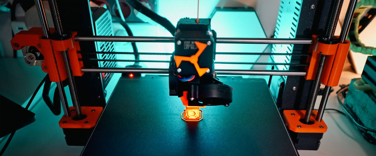
When we send a file to a 3D printer, it goes through a process called “slicing”. The slicing software divides the 3D model into thin horizontal layers – the “slices” – which correspond to the passes the printer will have to perform to build the object, layer by layer. This process turns the original 3D file into a set of instructions (often called G-code) that tells the printer exactly where to deposit material, at what temperature, at what speed, and many other parameters.
Essential characteristics of a 3D printing file
The quality of a 3D printing file depends on several crucial factors:
- Watertightness (watertight): the mesh must be completely closed, with no holes or openings, like a balloon that can hold water without leaking.
- Manifold: every edge of the mesh must connect exactly two faces, creating a mathematically consistent structure.
- Consistent normals: “normals” are vectors perpendicular to the faces that indicate which side is outside and which is inside. They must all point in the correct direction.
- Appropriate resolution: a mesh that is too coarse will not capture details, while one that is too fine could create huge files that are difficult to process.
- Watertightness (watertight): the mesh must be completely closed, with no holes or openings, like a balloon that can hold water without leaking.
- Manifold: every edge of the mesh must connect exactly two faces, creating a mathematically consistent structure.
- Consistent normals: “normals” are vectors perpendicular to the faces that indicate which side is outside and which is inside. They must all point in the correct direction.
- Appropriate resolution: a mesh that is too coarse will not capture details, while one that is too fine could create huge files that are difficult to process.
Main file formats for 3D printing
The landscape of 3D printing file formats is varied, with options that have evolved over time to meet increasingly sophisticated needs. Knowing the characteristics of each format is essential for choosing the one best suited to your project.
STL format
The STL file for 3D printing is the de facto standard in the industry and is supported by virtually every 3D printer on the market. Developed in the 1980s for stereolithography (hence the acronym STL), this format describes only the surface geometry of a three-dimensional object, with no information on color, texture or material properties.
The STL file for 3D printing is the de facto standard in the industry and is supported by virtually every 3D printer on the market. Developed in the 1980s for stereolithography (hence the acronym STL), this format describes only the surface geometry of a three-dimensional object, with no information on color, texture or material properties.
There are two variants of the STL format:
- Binary STL: More compact and therefore with smaller file sizes, ideal for complex models.
- ASCII STL: Human-readable (you can open it with a simple text editor), but it produces larger files.
Despite its popularity, the STL format has some significant limitations:
- It does not support colors or textures
- It does not include material information
- It does not handle metadata such as units of measurement or author
- It can produce very large files for complex models
- It has no built-in mechanism for detecting and fixing mesh errors
When preparing an STL file for 3D printing, it is essential to check that the mesh is “watertight”, that is, completely closed with no holes or gaps between triangles. In addition, wall thickness must be suited to the printing technology used, generally no less than 0.8-1mm for most FDM (Fused Deposition Modeling) printers.
OBJ format
When preparing an STL file for 3D printing, it is essential to check that the mesh is “watertight”, that is, completely closed with no holes or gaps between triangles. In addition, wall thickness must be suited to the printing technology used, generally no less than 0.8-1mm for most FDM (Fused Deposition Modeling) printers.
Unlike STL, the OBJ file can include information on colors and textures, making it possible to preserve the object’s visual appearance in addition to its geometry. It is like going from a black-and-white drawing to a watercolor: same shape, but with color and texture added.
The OBJ format supports both triangular and polygonal faces, offering greater flexibility in representing surfaces. It can also be accompanied by an MTL (Material Template Library) file that defines material properties such as color, reflectivity, transparency and texture.
The advantages of the OBJ format include:
- Support for colors and textures
- Greater precision in representing curved surfaces
- Compatibility with many 3D modeling and printing software packages
- Ability to include material information
However, not all slicing software fully supports the advanced features of the OBJ format, and some may ignore color and material information. When using an OBJ file for 3D printing, it is important to check compatibility with your specific workflow.
Advanced formats (AMF, 3MF)
As 3D printing has evolved, more sophisticated formats have emerged, designed specifically to overcome the limitations of traditional formats.
The AMF (Additive Manufacturing File) format was developed as an official ISO/ASTM standard to address the limitations of STL. This format supports:
- Multiple colors and materials
- Lattice and internal structures
- Mathematically represented curvature (not just triangles)
- Metadata such as units of measurement, author and copyright
- Built-in compression to reduce file size
Think of AMF as a souped-up version of STL that describes not only the shape of the object, but also how it should look and what it should be made of.
The 3MF (3D Manufacturing Format) format, backed by a consortium that includes Microsoft, Autodesk, HP and other industry giants, represents a further step forward. In addition to the features offered by AMF, 3MF adds:
- Native support in Windows operating systems
- Definition of support structures for printing
- Information on object placement and orientation
- Extensibility for future technologies
3MF was designed with the entire 3D printing ecosystem in mind, from modeling to production, ensuring that all the necessary information is preserved through the various steps of the workflow.
Despite their clear advantages, AMF and 3MF have not yet fully replaced STL, mainly because of market inertia and the vast installed base of software and hardware that supports the legacy format. However, their adoption is growing, especially in professional and industrial settings where the advanced features justify the transition.
Other relevant formats (STEP, IGES, etc.)
In addition to formats specific to 3D printing, there are many native CAD formats that can be used in the additive manufacturing workflow:
- STEP and IGES: Standard formats for exchanging CAD data, which preserve parametric and design information.
- VRML/X3D: Used mainly for color printing, they support detailed information on colors and textures.
- FBX and DAE (Collada): Common in the animation and video game industry, they can be adapted for 3D printing.
- PLY: Developed to store data from 3D scanners, it supports properties such as color and transparency.
The choice among the various 3D printing file formats depends on the specific needs of the project, the software used and the capabilities of the 3D printer. In many cases, it may be necessary to convert files from one format to another, a process that can introduce errors or loss of information if not performed correctly.
Preparing files for 3D printing
Properly preparing 3D printing files is as important as choosing the format. A perfectly formatted but poorly prepared file will still produce disappointing results or failed prints.
Initial modeling and design
The journey toward a 3D-printed object begins with modeling. This process can be approached in different ways, depending on your skills and the tools at your disposal:
- Professional CAD software: Programs such as SolidWorks, Fusion 360 or Rhinoceros offer precision and parametric control, ideal for technical and functional projects.
- Creative modeling software: Blender, Maya or ZBrush allow greater creative freedom, perfect for organic and artistic shapes.
- Software for beginners: TinkerCAD or SketchUp offer a simplified interface, accessible even to those taking their first steps.
- 3D scanners: They make it possible to capture existing physical objects and convert them into digital models.
During the design phase, it is crucial to take the constraints of 3D printing into account from the start. Some good practices include:
- Avoiding walls that are too thin (generally below 0.8mm for FDM)
- Considering print orientation to minimize supports
- Splitting large objects into components that can be assembled
- Providing appropriate tolerances for moving parts or joints (0.1-0.2mm)
Designing for 3D printing requires a different approach than modeling for visualization or animation. Every decision made at this stage will have a direct impact on the printability and quality of the final object.
Mesh checking and repair
Before sending a model to the printer, it is essential to check the integrity of the mesh. The most common problems include:
- Holes and openings: they create ambiguity about which part is inside or outside.
- Non-manifold faces: edges shared by more than two faces, physically impossible to produce.
- Flipped normals: they confuse the slicing software about the build direction.
- Intersections and overlaps: parts of the model that intersect in an unrealistic way.
Many software tools can identify and automatically repair these problems. Tools such as Netfabb, Meshmixer, or the repair features built into software such as Blender or Fusion 360 can save hours of frustration and wasted material.
The checking and repair process is like a preventive medical checkup: it is better to identify and solve problems before they cause complications during the printing “procedure”.
Optimizing for printing
Beyond geometric correctness, other factors affect the success of a print:
- Orientation: positioning the model to minimize the need for supports and optimize strength along the stress directions.
- Wall thickness: making sure all walls are thick enough for the printing technology used.
- Supports: generating support structures for overhanging parts with angles greater than 45° (varies by technology).
- Resolution and detail: balancing the level of detail with print times and the printer’s capabilities.
When preparing 3D printing files, it is also essential to consider the specific limitations of the technology used. For example:
- FDM printing struggles with very small details and requires consideration of the layering direction.
- SLA printing can produce finer details but requires attention to draining uncured resin.
- SLS printing offers greater geometric freedom but can present challenges for uniform cooling and powder removal.
An often overlooked aspect is scaling and units of measurement. Some software exports in millimeters, others in inches or arbitrary units. Always check that the model’s dimensions
Best practices for optimizing 3D files
Beyond proper technical preparation, there are best practices that can maximize the chances of success in 3D printing.
Technical guidelines
-
Minimum wall thickness: respect the limits of the printing technology:
- FDM: minimum 0.8-1.2mm
- SLA/DLP: minimum 0.5-0.8mm
- SLS: minimum 0.7-1.0mm
-
Optimal detail and resolution: balance the level of detail with processing times:
- Avoid excessively dense meshes where not needed
- Apply higher polygon density only in areas with critical details
- Consider the printer’s resolution (typically 0.1-0.4mm per layer)
-
Support considerations: design with a view to minimizing support structures:
- Avoid overhang angles greater than 45° when possible
- Orient the model to minimize the areas that require support
- Design support contact points in less visible areas
-
Reducing file size: optimize files to make them easier to manage:
- Apply controlled mesh decimation techniques
- Use binary formats instead of ASCII
- Remove unnecessary internal geometry
Pre-print check
Before sending a file to the printer, it is advisable to run a series of final checks:
-
Checklist:
- Correct dimensions and units of measurement verified
- Watertight and manifold mesh
- Minimum thicknesses respected
- Optimal orientation defined
- Supports generated and checked
-
Virtual print tests:
- Use print simulators to anticipate problems
- Check the model’s behavior layer by layer
- Estimate the time and materials required
-
Validation tools:
- Use specialized software such as Netfabb or Meshmixer
- Check for errors not visible to the naked eye
- Test structural integrity with analysis tools
A thorough pre-print check can save hours of time, expensive material and frustration, turning the 3D printing process from an uncertain attempt into a reliable, predictable procedure.
3D printing files are much more than simple data containers: they are the language that translates our creativity into tangible objects. Understanding the different formats, their characteristics and optimization methods is essential to fully exploit the potential of 3D printing.
Tools such as SHOWin3D by Shin Software further enrich the ecosystem, offering advanced solutions for viewing, interacting with and sharing 3D models before physical printing. This integration between the digital and physical worlds opens up new creative and production possibilities.
Whether you are a beginner hobbyist or an experienced professional, investing time in learning best practices for managing 3D files will reward you with more precise, reliable and higher-quality prints. In the world of 3D printing, as in many other fields, preparation is the key to success.
With increasingly accessible tools and constantly evolving formats, the future of 3D printing looks bright and full of possibilities. The bridge between imagination and reality has never been so solid and easy to cross.
Related terms
- STL (Standard Tessellation Language) – The most widespread format for 3D printing, based on triangular meshes.
- G-code – The instruction language used by 3D printers to build objects layer by layer.
- Watertight – The condition of a completely closed mesh, essential for correct 3D printing.
- Slicing – The process of dividing a 3D model into layers to generate the G-code file.
- Manifold – A topological property of a 3D model in which every edge connects exactly two faces, essential for printability.